Understanding a Rotating Apparatus
2024-01-22While working on a frivolous project I was looking for a way to connect wiring from a stationary base to a rotating platform, in this case under a Christmas Tree. I knew what I needed was a rotating contact of some kind, a bit like the concentric contacts in the base of fancy electric kettles.
I had no idea what that was called, but it turns out it is called a Slip Ring and there are many applications and you can just buy them on ebay!
Slip rings introduce a point where contacts can wear out and introduce resistance and noise. There’s been a lot of work on this over the last couple of centuries for things like lighthouses and antennas.
In my searching I had happened upon a patent which seemed to solve the problem without any kind of sliding contact at all, but I’d skipped over it because it involved gears and multiple rotation speeds. It was bugging me though: how on earth could it possibly work with no sliding parts at all?
The Patent
US Patent 3,586,413 by Dale A. Adams describes an “Apparatus for providing energy communication between a moving and a stationary terminal”.
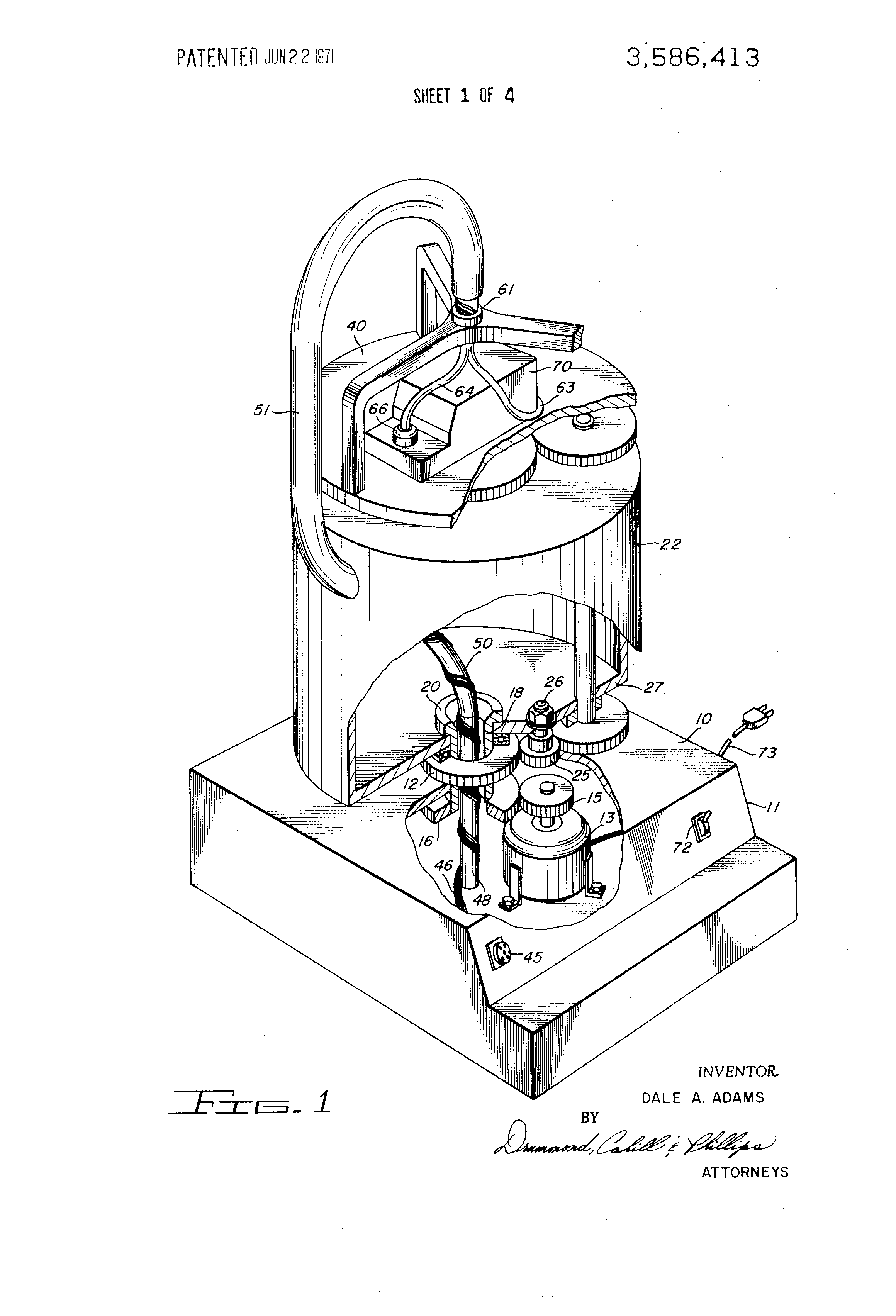 US Patent 3486413, Figure 1
Patents are written in weird language which attempts to both communicate an idea with an example and prevent its limitation by that example, but the following sentences in the patent description sum it up:
- A rotating support is mounted on a stationary surface for rotation about an axis.
- A rotating platform is mounted on the rotating support to permit relative rotation between the two.
- An electric motor is geared to rotate the rotating support and a gear arrangement is provided to drive the rotating platform in the same direction but at twice the angular velocity of the rotating support.
The patent includes a diagram of the geartrain required to drive the platform and support, which seems pretty complicated:
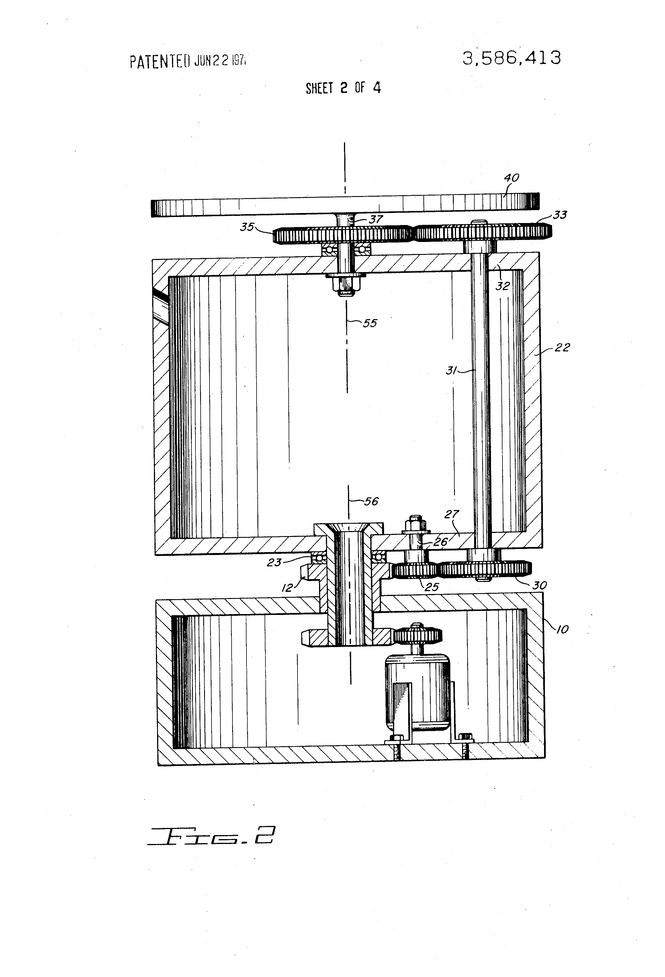 US Patent 3486413, Figure 2
However, the following patent text hints at the fact that the gearing is not essential to the idea:
- Similarly, the rotating platform may directly be driven and the rotating support may be connected thereto to rotate at the required velocity.
- If the electrical conductor or a conductor guide is to be used as the means for mechanically driving the rotating support or the rotating platform, then the ratio of velocities will automatically be achieved and the necessity for gear trains or other motion transmitting means is eliminated.
Simplifying
Okay, so let’s ignore the gears and any other parts which we can possibly ignore. What’s left?
Well, there’s a conductor which comes out of the base, around and over the top of the rotating platform. And there’s a support piece which fits between the base and the platform and guides the conductor.
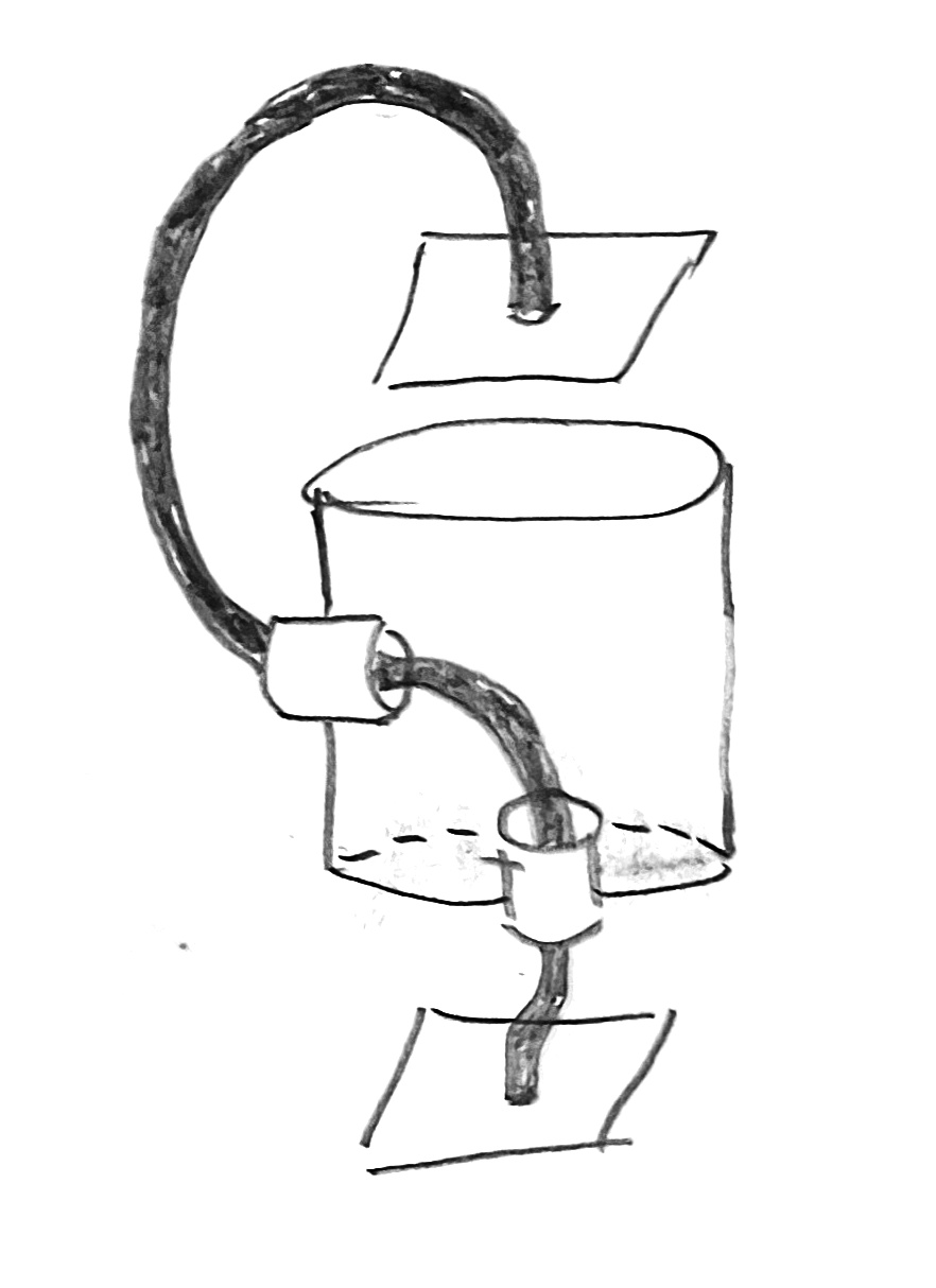 simplified diagram
The rotating platform rotates, obviously. The support piece rotates between the stationary base and the rotating platform, at half the speed the platform does. The conductor rotates within the rotating guide but somehow it does not itself twist. There’s a whole lot of rotation going on.
My head is spinning.
Thinking Flexibly
Sometimes it’s helpful to start from the middle. Let’s consider things from the point of view of the guide, as if the guide is standing still. Through the guide runs the flexible axle with a plate on each end, and the plates are rotating. All good?
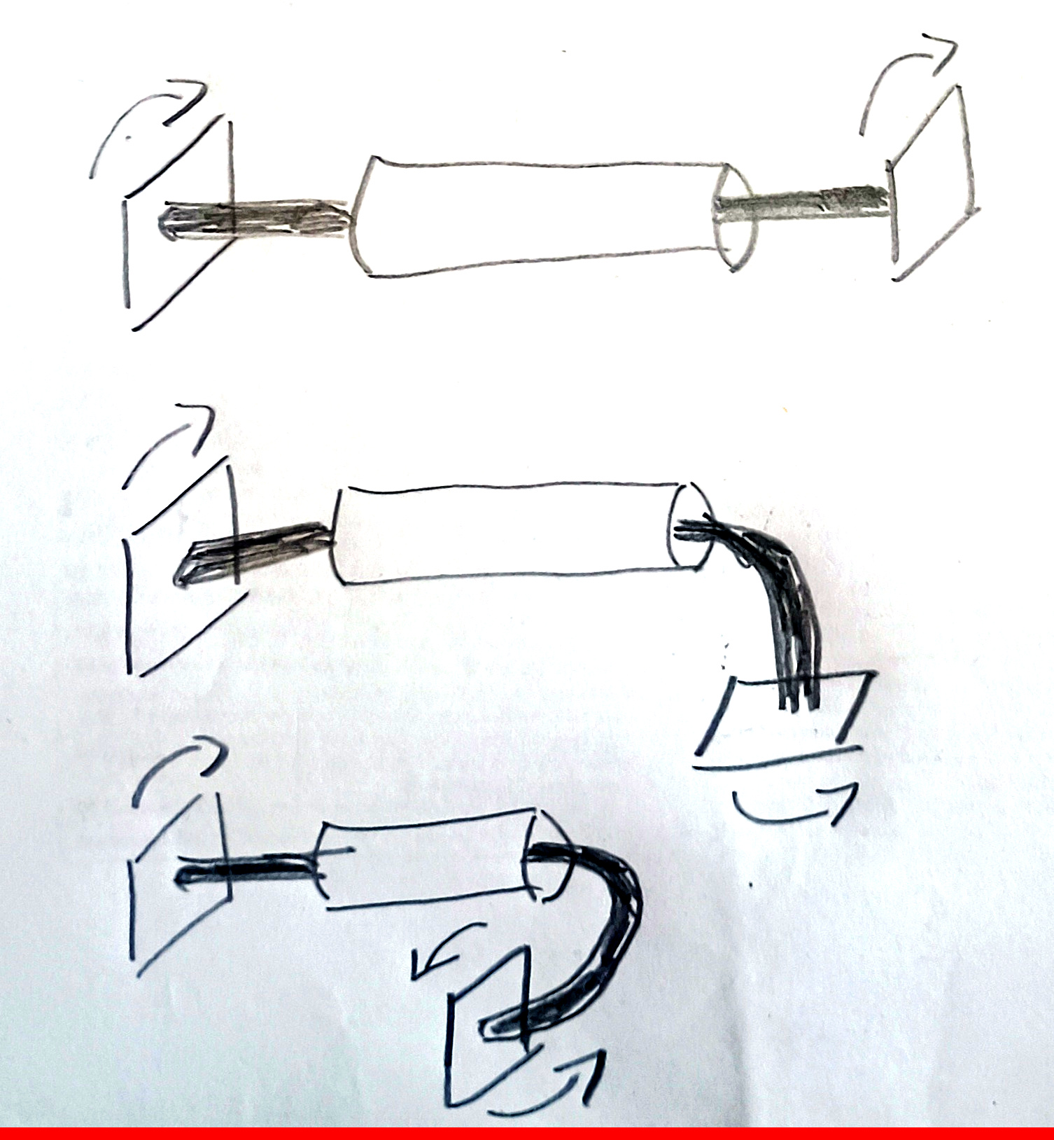 flexible axle
Okay, so now let’s flex that axle, while it’s still rotating. Both the plates are still rotating, even though they’re no longer in the same plane.
In fact, we can turn one of the plates right around on itself, and as the axle transmits the rotation the plate will now be rotating in the opposite direction to the other one.
Now, just add a cylinder between the two plates, holding the guide. The plates are rotating in opposite directions, relative to the cylinder, right?
Now imagine holding the bottom plate still. The cylinder is now rotating, and the top plate is rotating at twice that speed. Our flexible driveshaft is flexing, still rotating within the guide, but it is still not twisting.
The patented mechanism adds in a gear train to fix the ratio of rotational speed fixed rather than relying on a flexible drive shaft, but the basic idea is the same.
Related
It turns out it isn’t just me who’s stumbled onto this weird little concept. See also: