Geeetech A20T: Assembly and Configuration
2023-07-30I’ve been messing around with my cheap ALDI 3D printer for almost five years now and it’s time to upgrade!
I’ve just received my shiny new Geeetech A20T which has about 12× the build volume of the old printer, and has one extruder with three filaments feeding into it, letting it print designs in multiple materials and/or colours.
This article is about setting the printer up and getting it working. I’ve written a separate article with all the technical details of Multi-Material 3D Printing with OpenSCAD, Cura and the Geeetech A20T which might be interesting if you’re specifically into OpenSCAD and Cura but otherwise not so much.
Reviews, etc
On Youtube, there’s a Geeetech A10M review at Teaching Tech and six Geeetech A10M upgrades at Teaching Tech which give you some idea of how these printers work and whether they’ll be right for you.
The A20T User Manual gives you a pretty good idea of what you’re getting yourself into.
The Out-Of-Box Experience
It’s a winner so far. Everything is in the box, and the instructions are fairly good. Admittedly, the box arrived upside-down, eg: with the shipping label on the opposite end to the “this way up” end, but the courier were going to do that anyway. It’s very well packed into it’s box and doesn’t appear to have been harmed.
The instruction booklet is fairly good, there’s a couple of steps in the instructions which aren’t necessary as they’re already done for you (Y-axis wires were already plugged in, and the little bracket on the back of the print head already installed)
There’s a few spare screws, a couple of spare nozzles, various cleaning tools, replacement feeder tubes. And a little MicroSD card which turns out to have more documentation on board, and a USB adapator in case you don’t have one.
At the very end of the instruction book is a warning to check that the power supply is correctly set to 110V/240V. This is pretty easy to miss even if you read all the English instruction section before starting. It’s a lot more obvious in the PDF manual than the printed one which comes in the box. Putting the traditional warning sticker over the power inlet would be a nice touch.
Assembly
The only tricky bit really is attaching the gantry to the body. The easiest way seems to be to hang the body over the edge of a table so you can get to the screw from underneath while the gantry is in position. A spare pair of hands might be nice.
The tools in the box are mostly okay with the exception of the 4mm Allen key which you need to attach the gantry to the body. It’s too small to get a decent torque on those screws. But like me you probably have a few 4mm allen keys laying around.
I do wish they’d mentioned to attach the mylar bed before assembling the gantry to the printer body, that would have made it easier to line up. The mylar bed was well hidden in the packaging. I’d not realized this is just a fixed stick-on platform rather than a removable magnetic one. I might have to go back and buy the magnetic one now.
Also, before cable-tieing the wiring loom into place its a good idea to gently move the print head to its furthest position so you can judge where the cables will sit.
All up it took about an hour from the courier arriving to powering the printer up for the first time.
UPDATE: On my one, the two little screws which attach the Z axis nut to the X axis were very loose as shipped. Definitely check this and then run the Z axis up and down to make sure it’s moving smoothly and not binding anywhere.
Loading
Two of the three feeders on my printer are really hard to load filament into. Once you get the filament past the roller, it seems to hit a little restriction in there somewhere and get hung up on it, requiringa lot of wiggling around to get the filament fully into the tube.
The third one doesn’t seem to do this so perhaps I should pull one apart and have a look at what’s going on.
Appearance
There’s a couple of “untidy” things about this printer, for example the front end of the Y axis belt is out in the open air and the Y axis end stop is exposed at the back. It’s no big deal it just looks a little messy. I might print little covers for them.
The wiring looms are well protected in woven sleeves but they look quite messy too, some cable clips might be in order.
Printing Dimensions
The printer is advertised as 250 x 250 x 250 mm print volume but I figured I should check.
X axis
When homed, the X axis is at -10mm, and moves cleanly to +242mm before one of the print carriage screws fouls on the right hand gantry and the stepper cogs. This is no big deal but if you hit this point it will cause layer misalignment so the software really should know about this.
You can flip the screw around to avoid it hitting the ganty, but then the print carriage cable bracket fouls on the gantry at +244mm.
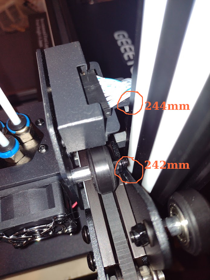 X-axis interference
It doesn’t look like this is going to be just my printer, so I guess I’ll put this in the profile as X_max = 240mm.
Y axis
The Y axis homes at -5mm and moves to +250mm before software stops it cleanly, so that’s nice.
Z axis
The Z axis homes to 0 and as supplied it moves to +249mm before the print head cable fouls on the gantry. This can be fixed by loosening the Z stop microswitch and moving it down ~2mm and leveling the print bed again.
Now it works fine and stops at +250mm.
Machine Dimensions
The specifications list the dimensions of the
printer as 442x447x480 mm
which isn’t quite correct either.
You’ll need to have a work top at least 500mm deep to allow the print bed to go all the way back with the front feet still on the table, and when fully forward the print bed will stick out a further ~75mm past that.
You’ll need at least 480mm width, and a bit more if you want to access the SD card slot on the right side, and there isn’t much room for the USB and power cables either.
The printer itself is about 520mm tall, but you’ll need at least 600mm to be able to load filament into the feeders. If you want to use this printer inside an enclosure you might want to consider relocating the feeders.
So overall, probably 600x600x600 mm would be an appropriate amount of space to allow. This stuff is important to get correct if you’re installing a shelf or cabinet for the printer.
And that’s not counting the three filament reels! The printer comes with three little desk-standing reel holders made of acrylic sheet which you can bolt together, but they’re probably not that convenient if you’re doing a lot of multi material printing.
Firmware
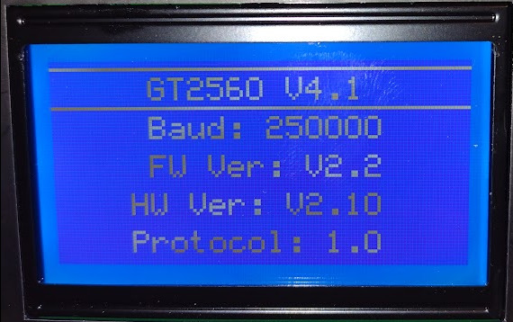 Hardware Info Screen
As packaged, the printer was loaded with Marlin 1.1.8 (2017-12-25) and no support for the 3DTouch sensor.
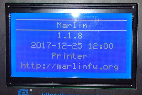 Firmware Version as supplied
I grabbed the upgraded firmware from the geeetech site but really, it’s prety annoying to ship a product with 5 year old firmware which the user then has to upgrade just to fully use your product!
There’s various instructions I found online which use Arduino or
Visual Studio to upload the firmware, but you really only need
to use avrdude:
avrdude -P /dev/ttyUSB0 -p m2560 -c wiring -D \
  -U flash:w:GT2560_A20T_HW4.1B_FW2.3.2__20210330.hex:i
After this upgrade … well, it’s still Marlin 1.1.8 but at least it’s a more recent build, and the 3DTouch menu is present now.
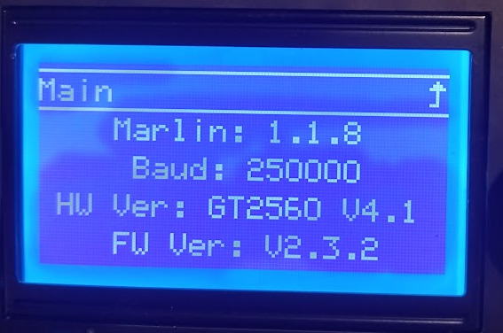 Upgraded Firmware Version
At some point I might have to look into upgrading to a more recent Marlin 2.x.
Noise
The head cooling fan is really quite noisy, it seems to be under quite a bit of load pushing air through the crowded print head so I doubt a baffle will help but perhaps a small duct might.
According to the Schematic there’s PWM on multiple fans, but only the print cooling fan seems to respond to commands.
M112 shuts the printer firmware down but doesn’t turn off the fans. Properly shutting the machine down remotely will still require a mains relay I suppose.
Front Panel UI
The display is big and bright and the click-and-turn input device is the same kind of thing the Aldi printer has, but without its annoying habit of shifting just as you click. You can’t actually see the display when the bed is fully forward though. I don’t expect to be using this much as I mostly drive the printer through Octoprint.
Automatic Bed Levelling
Along with the printer I ordered a Geeetech 3D Touch v3.2 Auto Leveling Sensor This is pretty fiddly to install and not supported by the firmware out of the box so trying it out had to wait until I got the firmware installed (see above).
It’s a pretty simple device: there’s a little linear servo which slides a pin in and out over a range of about 6mm. It sends back a signal to say if the tip is touching the build plate. Once it’s installed and configured it replaces the functionality of the Z-axis end stop switch, which you can remove.
So that lets it measure the build plate distance accurately. You then set it up so that the correct nozzle clearance (0.3mm or so) is when the fully-retracted sensor is about half way (3mm or so). There’s a parameter in the firmware which sets that exact value, so you can home the printer, lower Z to 0 and check the clearance, tweak the Z offset value and repeat until you get it spot on.
-
Level the bed as well as possible using the supplied slip of paper and the bed thumbwheels, etc.
-
Adjust the 3D Touch sensor until it’s 2-4mm off the build plate. About 3mm is ideal but don’t sweat it.
-
Unplug the Z-axis limit switch, plug in the 3D Touch sensor, activate 3D Touch in firmware.
-
Home the printer, lower the Z axis and then adjust the 3D Touch offset to get the offset correct. Repeat until it’s accurate.
-
Run the bed level program.
I’m not entirely clear from the schematic
whether the Z-axis switch has to be unplugged
on this particular printer: there’s provision for a separate Z0_MIN and Z1_MIN, and I
think Z0_MIN is wired to Z_MIN1 in the print head connector, but the actual switches
aren’t ever shown in the schematic. It would be nice to have an actual physical limit switch as
a backup!
UPDATE: After a lot of faffing about trying to get this working to my satisfaction, I’ve removed it from the printer and gone back to the good ‘ol microswitch-and-paper method! I’ll revisit 3D Touch at a later date.
Filament Runout Detection
The printer came with three filament runout detection sensors. In videos I’ve watched these little switches have seemed like they’re pretty wobbly but on this printer they bolt securely into place with two small screws and the wiring loom is already ready for them to plug in. The firmware supports them out of the box too, although you have to go into a settings menu to enable them. As a few people have noted, if you’ve got the switches activated then they all have to have filament in them for the printer to work, so keep a couple of bits of old filament around for any feeders which aren’t in use.
UPDATE: I’ve run or broken filaments a couple of times now, with Cura sending G-Code via USB, and what seems to happen is the heaters turn off but the print head keeps moving! So maybe this feature isn’t usable in this mode. I’ll have to investigate further.
CONTINUED: First Boats!
See also First test prints and calibration.
Don’t forget to check out the Multi Material Printing with Geeetech A20T article as well.