Multi-Material 3D Printing With OpenSCAD, Cura and the Geeetech A20T
2023-07-23I’ve been messing around with my cheap ALDI 3D printer for a few years now and it’s time to upgrade!
I’ve put an order in for a Geeetech A20T which has about 12× the build volume of the old printer, and has three filaments feeding into a single extuder, letting it print designs in multiple materials and/or colours.
I’ve written separate articles on assembling and configuring the Geeetech A20T and First prints with the A20T, this article is all about the technical details of getting a multi-material workflow set up with OpenSCAD and Cura.
OpenSCAD
I mostly use OpenSCAD to design stuff and OpenSCAD support for multi materials is not good (#1041, #1608.)
It’d be great to fix that, but in the meantime I need a quick solution so I can play with my new toy.
Erik Nygren has made a good start
with a method for selecting one part at a time using a multicolor() module
which checks a variable current_color for each part.
I wanted to get something similar working with Ultimaker Cura and to make it work without having to save a whole lot of separate STL files.
What I ended up doing was just defining several parts arbitrarily
called red and blue and green,
and at the bottom of the file include some code to select between them:
material = 0;
if (material == 0) {
   red();
   green();
   blue();
} else if (material == 1) {
   red();
} else if (material == 2) {
   green();
} else if (material == 3) {
   blue();
}
Then you can either alter the code to set material manually or call
OpenSCAD with a parameter to generate a file directly:
opencad -D material=1 -o project.stl project.scad
It might seem counterintuitive, but because of the way OpenSCAD programs
declare variables, the -D material=1 option can override the value set by
the code material = 0;.
O tempora, o mores!
I’d like to come up with a nicer mechanism for doing this in OpenSCAD. Ideally there would be a mechanism to read out the names of the top level modules, and a mechanism to select one module to render.
Intersecting Volumes
Cura 5.4 doesn’t handle intersecting volumes nicely at all, exporting weird alternating layers where the volumes intersect.
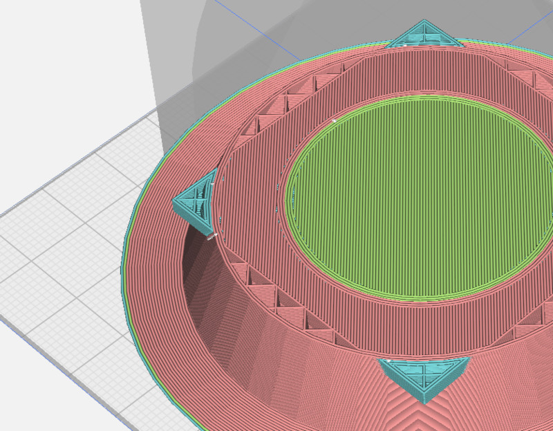 layers behave weirdly when volumes intersect
So instead make sure you subtract layers from each other before emitting them. We alter our previous code like so:
material = 0;
if (material == 0) {
    red();
    green();
    blue();
} else if (material == 1) {
    difference() {
        red();
        green();
        blue();
    }
} else if (material == 2) {
    difference() {
        green();
        blue();
    }
} else if (material == 3) {
    blue();
}
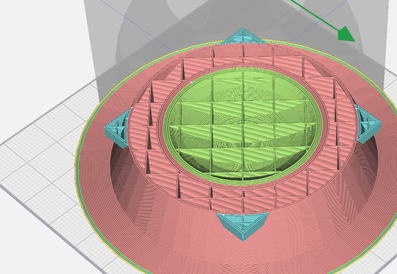 layers behave better when the volumes don’t intersect.
Note that there are still extraneous interior walls though, see below for details.
UPDATE: Cura 5.4.0 seems to be able to work this out for itself if setting “Remove Mesh Intersection” is not set! Maybe that’s a bug. But perhaps this step is unneccesary.
Exporting as AMF
So far, I’ve used STL to get my models from OpenSCAD to Cura, but it’s pretty limited and a bit of a pain to work with. There are more modern formats available. I had a look at 3MF but it a mess of ZIPped XML and so instead I’ve been working with AMF.
AMF is a relatively simple XML format. It’s an “Open Standard”, but sadly
it’s the kind of “Open Standard” which
costs sixty-three bucks to download
so instead we’re gonna go on guesswork and other people’s code.
Just looking at the AMF file, you can tell that it contains a pretty
simple hierarchy of <amf> -> <object> -> <mesh> -> <vertices> and <volume>s
so it’s not hard to guess what everything does.
Then we can just iterate through the materials from the command line
using the -D var=val command line option and get OpenSCAD to export
each material to a different .amf file:
openscad -D material=1 -o temp1.amf project.scad
openscad -D material=2 -o temp2.amf project.scad
openscad -D material=3 -o temp3.amf project.scad
Since we can manipulate AMF files pretty easily we can then combine those files into one file which can be importing into Cura.
combine_amf.py:
#!/usr/bin/env python
import sys
import xml.etree.ElementTree as ET

# XXX should handle units other than millimeters
# XXX probably should keep per file metadata
# XXX possibly should define materials per input file
# XXX possibly could unify vertices and produce multiple volumes in a single object

xout = ET.Element('amf', attrib={'unit': 'millimeter'})

obj_id = 0

for fn in sys.argv[1:]:
    et = ET.parse(fn)
    root = et.getroot()
    assert root.tag == 'amf'
    assert root.get('unit') == 'millimeter'

    for obj in root.findall('object'):
        obj.set('id', str(obj_id))
        xout.append(obj)
        obj_id += 1

ET.ElementTree(xout).write(sys.stdout, encoding='unicode', xml_declaration=True)
Rather than doing these steps manually we can use a bash script:
mmexport.sh:
#!/bin/bash
set -eu
SOURCE=$1
TARGET=${2:-${SOURCE%.*}.amf}
TEMPDIR=`mktemp -d`
for MATERIAL in 1 2 3 4 5 6 7 8 9 10 11 12 13 14 15 16; do
    echo -e "---\nEXPORTING MATERIAL $MATERIAL"
    openscad -D material=$MATERIAL -o $TEMPDIR/temp$MATERIAL.amf $SOURCE || echo "FAILED"
done
echo -e "---\nCOMBINING INTO $TARGET"
./combine_amf.py $TEMPDIR/temp*.amf > $TARGET
echo -e "---\nDONE\n"
rm -r $TEMPDIR
Some examples
I’ve uploaded some multi-material OpenSCAD examples which use these methods, although I’m still messing around trying to work out “the best way” …
Importing into Cura
Ultimaker Cura can import AMF files, and when we import a multi-object AMF file as generated by the script above it appears as a single “grouped” object. All the materials are locked together to prevent misalignment.
We can still select individual pieces within the group using Control-Click, and then assign them to different extruders manually, one at a time.
Beware, if you decide to ungroup the pieces they may become misaligned as Cura will “drop” each piece to touch the print bed. To prevent this, control-click each individual piece and make sure “Drop Down Model” is turned off on every one before ungrouping the pieces.
It sure is tedious selecting each of those pieces. It would be nice if there was a way to automate this. Maybe there is, in some other format like 3MF?
Printing on the Geeetech A20T
I’ve written a separate article on assembling and configuring the Geeetech A20T.
The A20T has three filaments feeding into a single extruder nozzle. Cura 5.4.0 has a built-in printer definition for the A20T which supports the three physical extruders.
The firmware can also do mixing and fading between the physical extruders, by configuring “virtual extruders”, each of which can have its own ratio of filaments. By default Cura only supports the three physical filament feeders, but an extra configuration file can be added to support up to eight (or maybe 16) in total.
You can’t edit the built-in printers but you can add new ones. I’m not sure why this has to be so damn tricky or whether there’s a better way to do all this, but I’ve been able to modify the existing definitions a bit to allow more extruders.
You can unpack these files into your resources directory
(eg: $HOME/.local/share/cura/5.4/ on Linux,
something like %APPDATA%\cura\5.4\ on Windows I think,
which might be under C:\Users\YOUR USERNAME\AppData\Roaming\)
This one should give you a new “A20Tx8” printer with eight extruders:
A20T with eight extruders (A20Tx8) printer definition
… or an “A20Tx10” printer with ten extruders:
A20T with ten extruders (A20Tx10) printer definition
The Cura interface becomes pretty cumbersome with this many extruders though. I tried setting up different filament colours as well … so lots of generic PLA filaments with different colours in their names and different colours in the preview … but it didn’t work all that well as you need to assign one filament definition per extruder and you need to make them different colours, and unless you’ve got some connection between the colour of the filament in Cura and the colour of the mixed filament on the actual printer it’s just going to get confusing.
Setting up Mixing (in G-Code)
Virtual extruders are set up in the printer settings G-code using the M163 and M164 commands.
Note that G-code standardization is quite broken across different brands of printer and different firmwares. There’s multiple interpretations of even basic stuff like tool changes and lots of optional features which your printer may or may not support. If you’re using something other than a Geeetech printer the required G-code may be subtly different.
Marlin supports up to 16 “virtual tools” by default
(see MIXING_VIRTUAL_TOOLS), numbered from 0 .. 15.
Each of those has a mapping to a different mix of the
real tools, numbered (in my case) 0 through 2.
For example these commands select a 50/30/20 mix of the three filaments in the real extruders 0, 1 and 2, and assign that mix to a “virtual tool” 3:
M163 S0 P0.5
M163 S1 P0.3
M163 S2 P0.2
M164 S3
You can reassign virtual tools 0, 1 and 2 as well!
Once these virtual tools are set up, Cura will automatically
use them for the different extruders using the tool change
commands T0 .. T7. So by fiddling with the “Start G-Code”
in the printer settings, you can set up several extra
colour mixes so for example this sequence would set up
tools 3 through 7 as mixes of tools 1 and 2 (the second
and third filaments), so you could for example load white,
red and blue and print in white and several shades of purple.
M163 S0 P0
M163 S1 P0.84
M163 S2 P0.16
M164 S3

M163 S0 P0
M163 S1 P0.67
M163 S2 P0.33
M164 S4

M163 S0 P0
M163 S1 P0.5
M163 S2 P0.5
M164 S5

M163 S0 P0
M163 S1 P0.33
M163 S2 P0.67
M164 S6

M163 S0 P0
M163 S1 P0.16
M163 S2 P0.84
M164 S7
Using M166 should let you assign a Z-gradient to a tool as well!
It’d be nice to define a Cura plugin to make this a bit more accessible. There’s a Colormix Plugin for two-into-one mixes, which might be a good start to work from. But the Cura post-processing plugin interface looks pretty seriously limiting. Oh, well, let’s wait and see.
Outstanding Issues with Multi-Material Printing in Cura
-
Doesn’t understand when you don’t care what colour the infill is.
For a lot of models you don’t care what colour the infill is and it can go ahead and purge the old colour into the infill instead of a separate purge bucket. You can set infill per object but it’ll still want to purge between colours.
Perhaps a list of “infill extruders” should be settable per tool. Then, when changing from outline to infill, if a tool’s outline extruder is also one of its infill extruders, the colour change can happen just inside the infill, and then back just before resuming the outline. If the outline colour is the same as the first infill colour, no change is necessary.
For multi coloured prints there might be a bit of extra changing back and forth between outline and infill required to make this happen efficiently.
-
Builds internal walls between colours
If you define two intersecting solids, Cura still constructs solid walls between them even though those walls are doubled up and also hidden from view. This is probably what you want if, eg: printing a PLA wheel with an integral TPU tyre, but not necessary if you’re just printing a multicoloured design where this internal structure is just an artifact of the way you designed it.
I have a terrible work-around for this; see below
-
Doesn’t harness the full potential of colour mixing
Limiting the print to a set of fixed ratios in the form of virtual tools simplifies the situation but also misses out on some of the capabilities of the printer to continuously adjust the mix as it prints. Use of colour gradients in some situations might actually be quite pretty!
A Terrible Workaround For Interior Walls
Cura can already print infill in a separate extruder but it doesn’t know how to eliminate interior walls, which will be printed in the surface colour.
So this is a workaround using OpenSCAD to separate the hidden interior from the surface layers so they can be specified separately:
-
Create a volume which is just a smidge smaller than the sum of your actual volume. There are smarter ways, such as having a working 3D offset command, but this probably works well enough:
module everything() {
    red();
    green();
    blue();
}

module interior() {
    intersection() {
        translate([1,0,0]) everything();
        translate([-1,0,0]) everything();
        translate([0,1,0]) everything();
        translate([0,-1,0]) everything();
        translate([0,0,1]) everything();
        translate([0,0,-1]) everything();
    }
}
It’d be nice to have a 3D equivalent of offset or possibly a minkowski difference, but this is an approximation. If there’s holes in the corners, add more translations like
translate([1,1,0]) everything();but it gets very slow. -
Subtract this interior volume from every part:
if (material == 1) { difference() { red(); green(); blue(); interior(); } } -
Also render the interior volume as its own material:
} else if (material == 4) { interior(); } -
Combine AMFs and set the interior volume as your infill material, with only a single wall, top and bottom layer. You can’t select the interior volume by clicking on it, but you can set the material for the whole grouped component to the infill material, and then change each of the visible components individually to other materials.
The interior volume now takes up most of the space, with the other materials just forming a thin shell of 2-3 layers surrounding the outside.
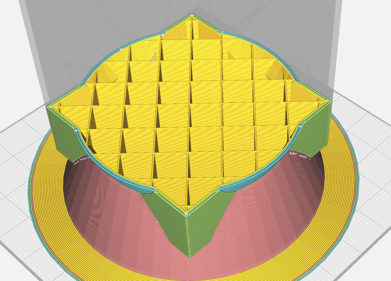 layers with the internal volume removed
or if your design works well this way, you could beef up the shell a little and leave the core out, just letting Cura add support where necessary.
This feature really belongs in Cura, not OpenSCAD, but doing it this way is expedient.
It’s quite possible that this is already an option somewhere in Cura’s extensive set of “Mesh Fixes”, “Special Modes” or “Experimental” settings. If you find it, let me know!
To Be Continued
Now it’s arrived I’ve written about assembling and configuring the A20T and I’ll keep working on the multi material stuff as I go.