CCCP: the Computer Controlled Camera Project
2026-07-24 — 2026-08-20This is a project to get a camera and lens controlled directly from software. There are various ways to do this, including remote control of a DSLR or mirrorless camera, but in this case I’m just trying to control the camera hardware directly, as a learning experience if nothing else.
The Camera
This is an HDMI camera I bought off Ebay as a circuit assembly / inspection microscope. The nice thing about this camera is it outputs HDMI so you can use it directly with a monitor or TV at very low latency.
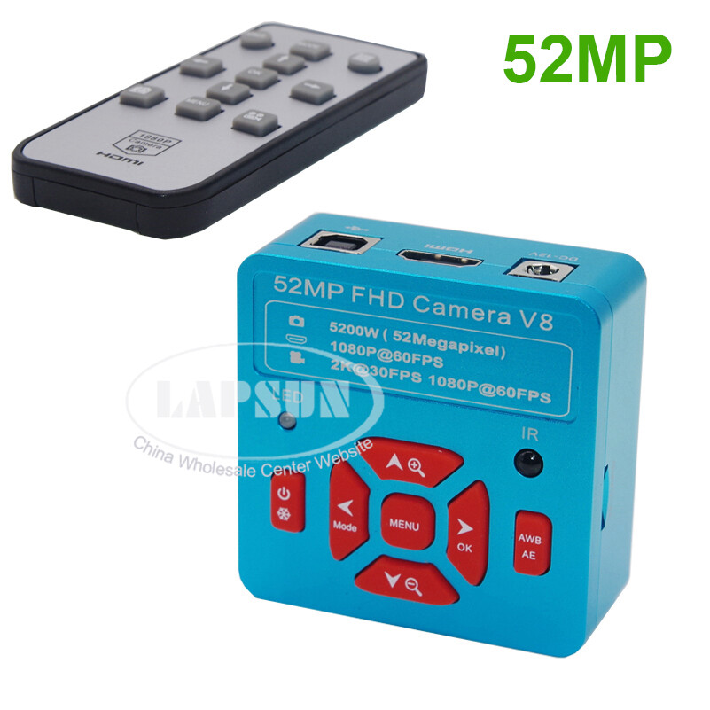
The camera is advertised and labelled as “52MP FHD Camera V8” but when zooming to “7.0x” in it’s pretty clear that it isn’t a 52 MPix sensor, and at this high level of zoom it’s actually interpolating pixels. It is more or less this YW5607 which I note advertises a more realistic 16Mpix which would correspond to a 2.8x zoom.
Zooming
These guys were quite helpful, unfortunately this camera has a couple of things it doesn’t do which I need it to for this project:
- When powered through the DC power port, it doesn’t turn on automatically or via the remote control.
- When powered through the USB port, all button controls and remote controls stop working (including zoom)
- When powered through the DC power port and not the USB port:
- the button controls work
- the USB data lines (using a split cable) don’t
- If you power from DC and zoom the image in, then apply power on USB, you can see the zoomed image over the USB interface.
- The maximum resolution supported by this camera on UVC is 1920x1080 and it doesn’t seem to expose “controls” for zooming.
So, to make this camera zoomable remotely, I’ll need to toggle the USB power on and off.
- Turn USB power on to wake camera.
- Turn USB power off and then send IR codes to zoom in or out
- Turn USB power back on to connect to camera.
- Turn USB power off and send IR codes to power off.
This is annoying! This camera might go back to being an inspection camera …
Other Cameras
I’ve also ordered a more specialized CS-mount camera. It’s based on the Sony IMX577 and should be able to stream 3840 × 3024 at 20FPS over USB 2.0. Hopefully it’ll also let me zoom etc using UVC controls.
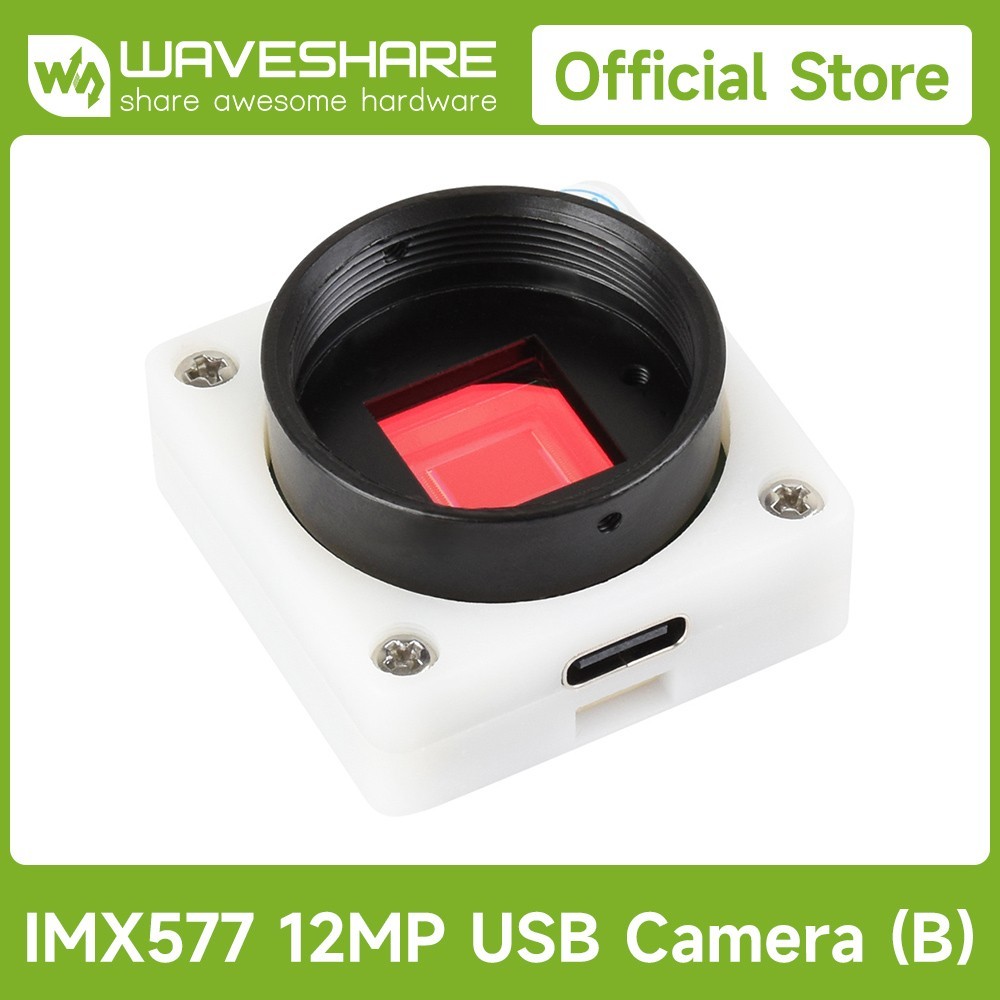 IMX577 based USB camera from Waveshare
There are heaps of similar cameras around using various flavours of “CSI”, and which support assorted Raspberry Pi and Nvidia Jetson boards, but I’m not sure how the different versions interoperate and what boards will be compatible in the future and using USB saves me worrying about all that.
There are also a heap of cameras around which use an “M12” or “S-mount” lens, which uses a plastic M12x0.5 thread to retain and focus the lens. I already have a couple of CS mount lenses though …
The Lens
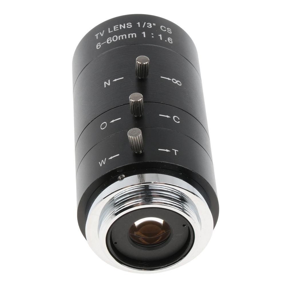 From Ebay.
This is a 6-60mm zoom CS-mount1 lens which opens out to f/1.6. The image circle is 1/3” whereas the camera is 1/2.5”, so fractions being fractions, at some focal lengths you can indeed see vignetting or even the edges of the lens in the corners of the image, where the image circle is smaller than the sensor.
The outside of the lens barrel is 36mm. There are three rotating controls each of which rotate about 90⁰ and they have little M2 thumb screws to secure them in place at a fixed position.
Ring, ring …
The middle ring is labelled “O ←→ C” and is straightforwardly the aperture, from a maximum f/1.6 at “O” to completely closed at “C”. As the aperture closes it appears to be three blades leading to quite amazing bokeh
The other two rings are a bit weirder. The front ring is labelled “N ←→ ∞” suggesting this is focus from near to infinity and the rear one is labelled “W ←→ T” suggesting this is zoom from wide to tele. In use though, the front one acts more like a zoom and the rear more like a focus adjustment. I was having some trouble coming to grips with how this actually worked so I ended up making a test jig to let me experiment.
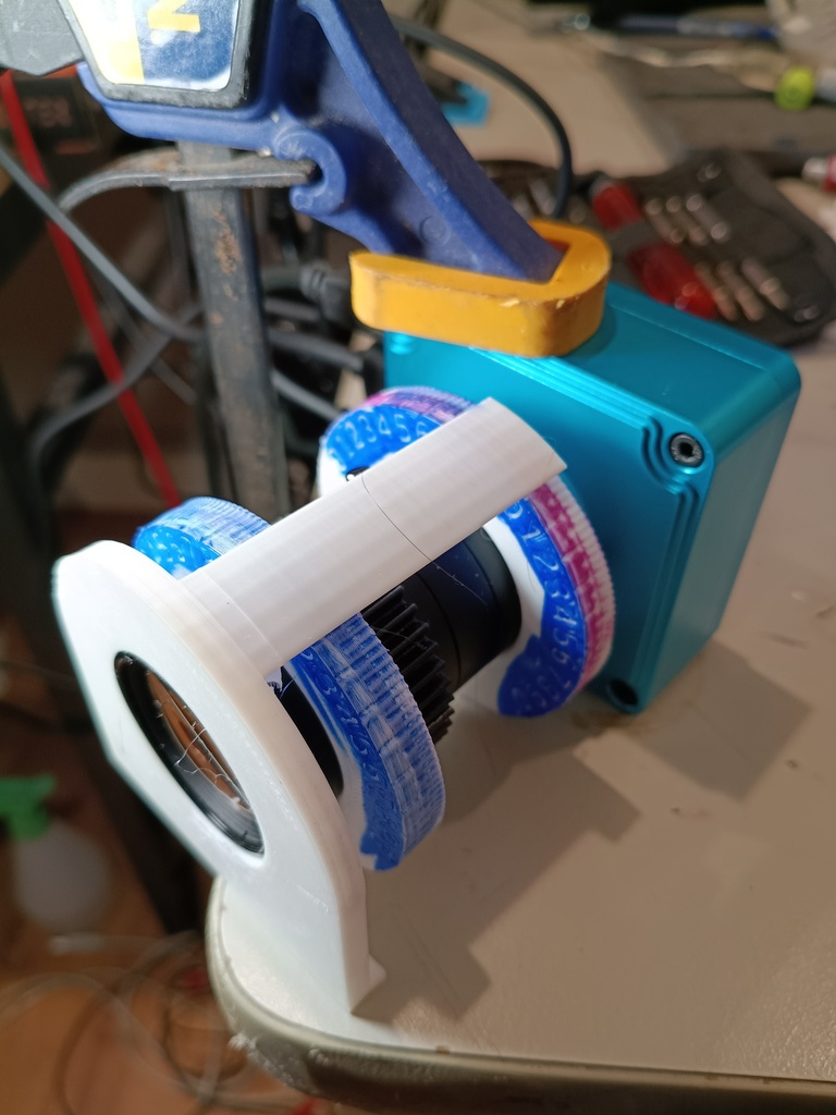 test jig for measuring lens behaviour
Two big plastic rings and a pointer make it easy to adjust and measure the position of each ring to within a couple of degrees: the rings are very sensitive so even a 1⁰ change makes a noticable difference.
I set the front ring to various angles, and used the rear ring to focus on fixed targets at 3.0 meters, 1.5 meters and 0.75 meters, and recorded the angle of the rear ring. I didn’t measure the actual zoom focal length but the lens claims 6-60mm which would be 36-360mm in 35mm equivalent which seems about right.
| front ring | rear ring (300mm) | rear ring (150mm) | rear ring (75mm) | zoom |
|---|---|---|---|---|
| 0 | 28.75 | 28.75 | 30 | tele |
| 5 | 32.5 | |||
| 10 | 36.25 | 37.5 | 37.5 | |
| 15 | 40 | |||
| 20 | 43.75 | 43.75 | 43.75 | |
| 25 | 47.5 | |||
| 30 | 51.25 | 52.5 | 52.5 | |
| 35 | 55 | |||
| 40 | 57.5 | 60 | 62.5 | |
| 45 | 62.5 | |||
| 50 | 65 | 67.5 | 70 | |
| 55 | 71.25 | |||
| 60 | 72.5 | 75 | 80 | |
| 65 | 75 | |||
| 70 | 80 | 85 | ||
| 72.5 | 76.25 | |||
| 75 | 75 | |||
| 77.5 | 72.5 | |||
| 80 | 68.75 | 75 | 85 | |
| 81.25 | 65 | |||
| 85 | 57.5 | 65 | ||
| 87.5 | 48.75 | |||
| 90 | 38.75 | 50 | 71.25 | wide |
all measurements are ±1⁰ or so
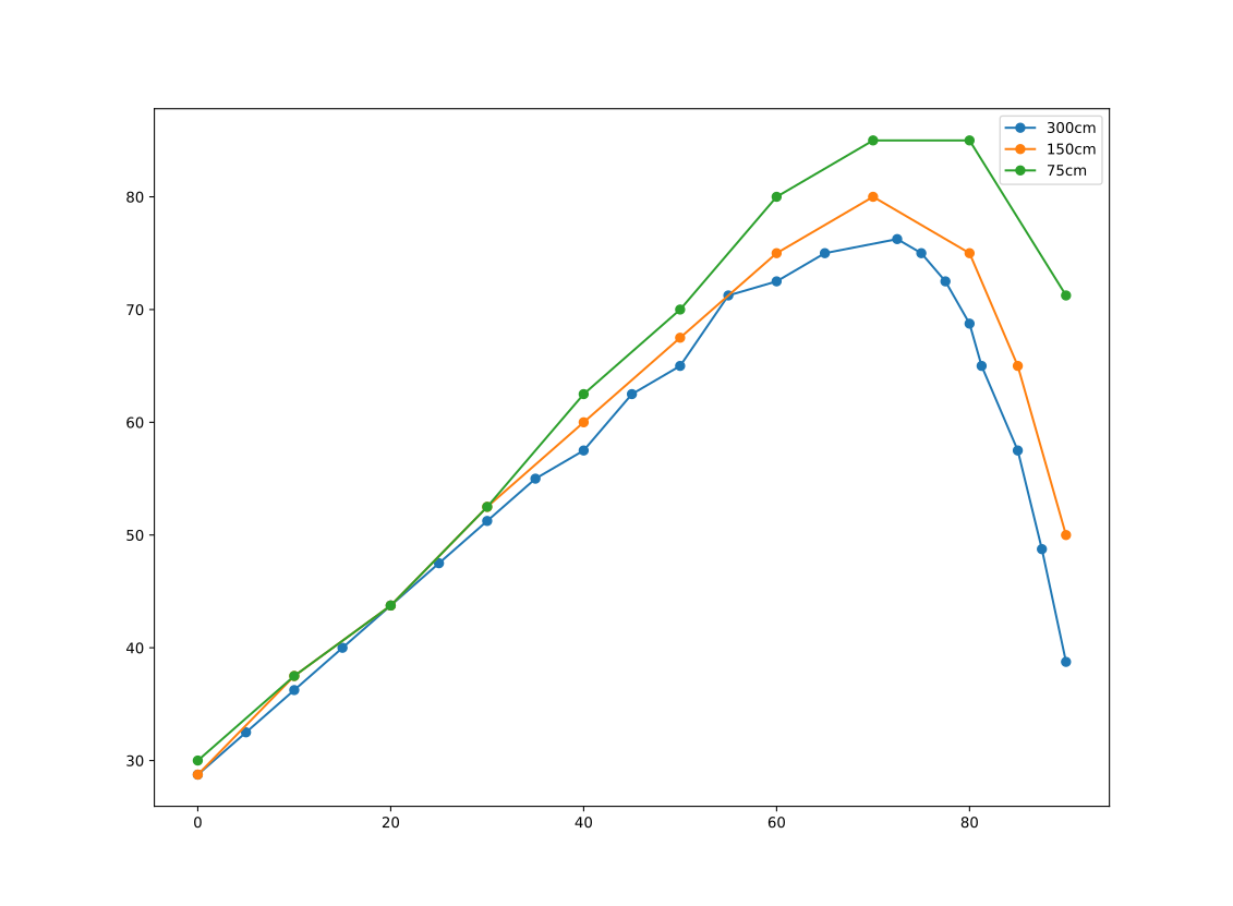 ring1 vs ring2
The relationship between the two is not linear! The angle of the rear ring rises along with the angle of the front ring, until it slows and rapidly reverses. You can confirm this experimentally: with the rear ring set to 60⁰, the image is in focus at two widely different settings of the front ring, with different zoom levels.
By picking an arbitrary ‘zoom’ axis for both rings to be functions of, and assuming one was a simple parabola, I was able to fit a cubic to the other:
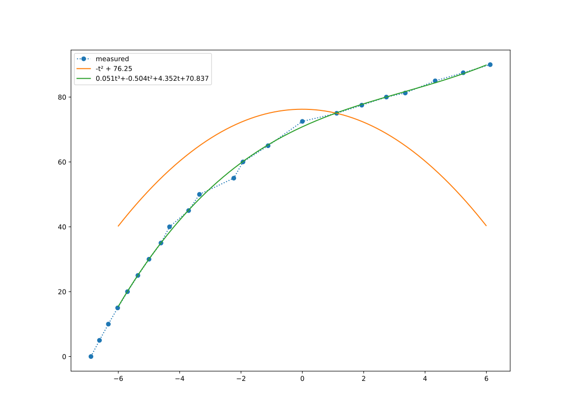 fitting curves compared to an arbitrary ‘zoominess’ axis
This is pretty arbitrary, of course: a more elegant equation and a better fit is likely possible but I’m going to come back to this once things are automated.
… why don’t you give me a gear.
To let the computer control the lens, I 3D printed a gear which fits tightly onto the ring and used the existing thumbscrew to secure it to the ring. Because of the additional spacing, the screws just attach the gear to the ring and don’t prevent the ring from rotating freely.
3d printed spur gears work amazingly well, I’ve used them in previous projects and with the right print settings they can be quite strong and reasonably efficient. There’s a nice OpenSCAD gear library which makes it easy! I could write a whole article just on spur gears and perhaps some day I will :-)
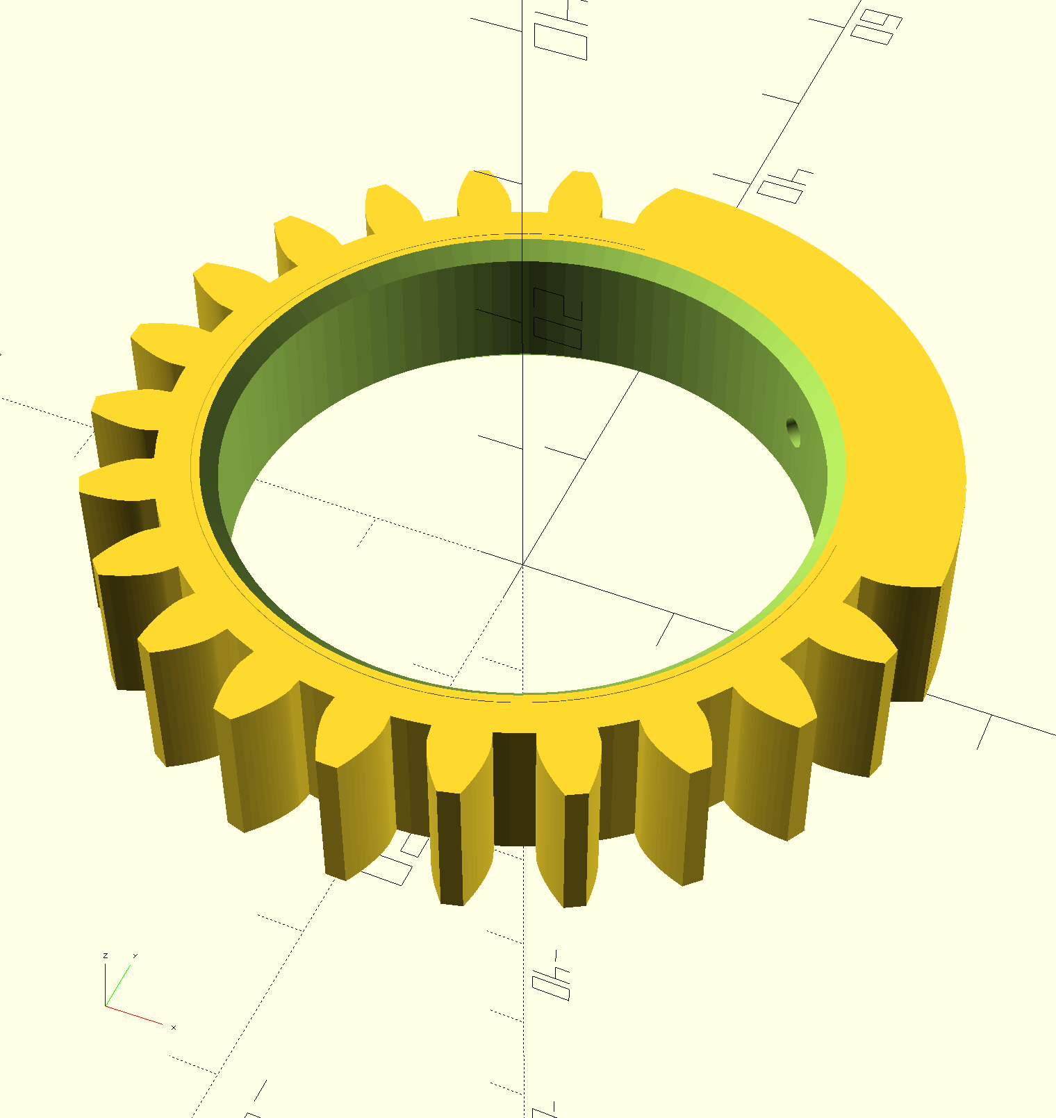 lens gear designed in OpenSCAD
I drive the gear with a small [RC servo](https://en.wikipedia.org/wiki/Servo_(radio_control). The servo I’m using is a Tower Pro 9G SG90, these turn about 180⁰ where the ring only turns 90⁰, so I use a 1:2 gear ratio to match them together.
RC Servos are cheap and cheerful and not particularly accurate or precise, but they do have a handy amount of torque for their size and just need a single pulse signal to tell them what position to go to. This makes them very easy to control from a microcontroller IO pin using PWM … depending on the microcontroller you could get 8, 10 or even 16 bits of resolution.
The front ring can now be moved quite easily across its full range.
Next: add a second servo! By controlling the two rings separately, and plotting out focus curves at other distances, I should be able to focus and zoom the lens accurately.
I could maybe even squeeze in a third servo for aperture. Computer control of aperture would be quite nice because the computer could then change the aperture, and thus the depth of field, while autofocussing.
Microscope Lenses
I also have a 100x2 C-mount3 microscope lens which is also getting a motorized focus. The microscope lens one only has the one ring so is a little more straightforward. On the other hand, its focus ring rotates about 3½ turns rather than ¼ of a turn so a stepper might be a better idea than a servo.
This is an earlier prototype using a large servo and chunky gears. It clamps onto the lens barrel and focus ring using self-tapping screws in the plastic. I’ll need to find a better way to support continuous rotation.
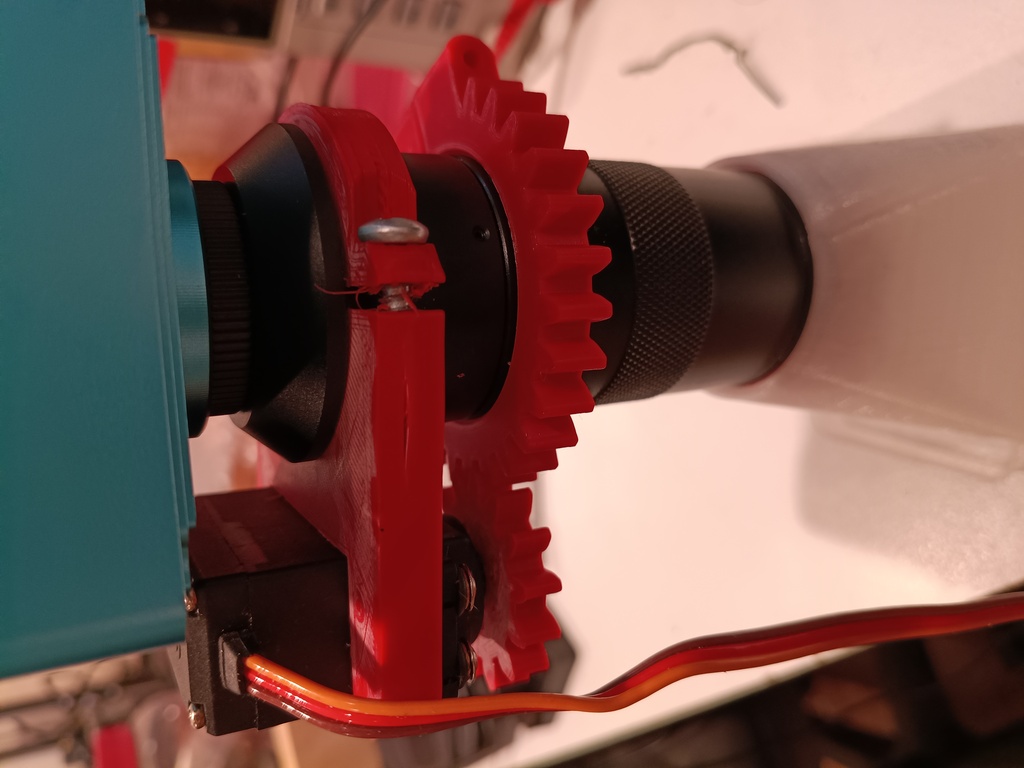 Microscope lens with servoed focus
I also have some microscope objectives around here somewhere and I’d like to try getting them working with the camera sensor. Those are fixed focus though so they’ll require a very precisely moveable Z axis.
Real Camera Lenses
Real camera lenses make these adjustments using ultrasonic motors which wrap right around the lens. It’d be a fun project to reverse engineer a micro-four-thirds power zoom lens for this purpose, but that’s a different project for a different time.
Autofocus
I’d like to explore getting autofocus working … part of the inspiration for this project was to get the microscope camera autofocussing to make it easier to work with. Because the depth of field is very shallow, varying the focus could also be used to reveal the 3D structure of the structure being observed.
This paper looks particularly interesting:
Updates 2026-07-29
I’ve made a new microscope mechanism with a small geared stepper motor and finer pitch gears. Rather than clamping on, the motor bracket and the gear use tapered wedges to grip the lens barrel, and this seems to have worked quite well, the layer lines keep everything securely locked together.
You can get the 3D model files here or the OpenSCAD source on github
I’ve got to say, I’m not a big fan of these 28BYJ48 steppers,
which somehow manage to draw 5V / 400mA, have a ~64:1 reduction gear and still
not have enough torque to pull the skin off a rice pudding.
There’s also a lot of backlash in the drivetrain.
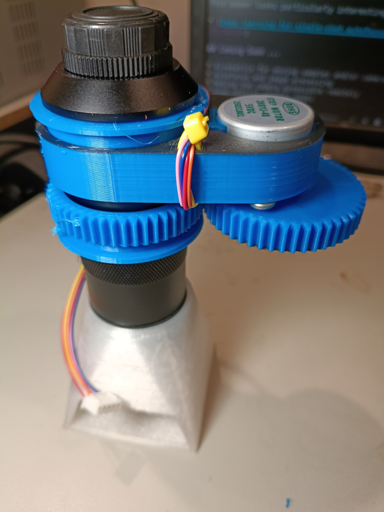 new microscope setup
Still, it should be enough to grab a stack of JPGs to try out autofocus algorithms, while I look around for an affordable source for NEMA 8 motors or similar.
I also need some kind of stall detection or endstop detection or whatever, for when the lens hits the end of its focus range. And maybe a detector for when the gear falls off.
Updates 2026-08-08
The Waveshare IMX577 Camera arrived and it’s much nicer to work with than the other one, as well as being smaller.
I also took some images of a ruler to measure the pixel pitch, and images with the microscope lens on the Sony IMX577 camera sensor are about 666 pix/mm. The camera sensor pixels are 1.55μm square, which means this lens is almost exactly 1x.
Using V4L2 it can capture the whole frame at 3840x3024 at 20fps, or zoom in on a smaller part of the frame for a higher framerate.
I’ll be writing lots more about microscope lenses soon.
Updates 2026-08-20
More stuff on stepper motors as I consider whether I’d be better off focussing by moving the entire camera and lens rather than trying to turn a rebellious helicoid. There are advantages and disadvantages.
I also ordered a much nicer looking geared stepper which will possibly become the focus motor one way or another.
Coming Soon …
- Kinematics for moving samples and/or cameras smoothly
- Autofocus and image processing
- Making the camera accessible remotely
- Some optical theater magic
-
Sadly CS lenses don’t lend themselves to mounting on other cameras as their focal plane distance is very short indeed (12.526mm), even compared to say Micro 4/3’s 19.25mm. The ones you see people using with mirrorless cameras are “C-mount”, which are the same thread but 17.526mm focal plane distance, which you can get away with by recessing the lens a couple of mm into the camera body. ↩
-
Much as with 10x programmers, the “100x” is bullshit.
This lens is *maybe* as powerful as a 8x microscope objective.See updates. The nominal 100x includes the magnification between the 1/2.5” camera sensor and a great big monitor. ↩
-
C-mount lenses can mount on a CS-mount camera using a 5mm spacer (see above), but not vice-versa, or at least not without limiting the focal range. ↩