Three-axis motion with GRBL
2026-08-19 — 2026-08-24For an upcoming project I want to get three axis motion working with linear stages which use a stepper motor and a trapezoidal thread to move in a very accurate way.
Stepper Stages
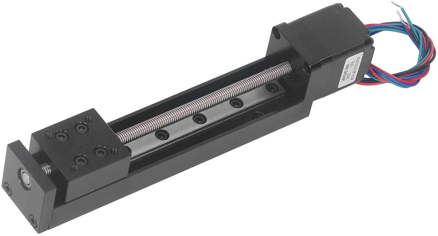 photo: ebay listing
I used three of these stages from
celinahotoin on ebay.
They have a 200-step-per-revolution NEMA111 motor and a Tr6x2(P1) trapezoidal
thread.
The thread has a 1mm pitch but a “double start” so it moves 2mm per
revolution
resulting in 100 steps per mm (not 200 like the listing said).
As shipped the bearing end plates were a little misaligned on two out of the three stages, causing them to jam near the far end of travel. To fix this, just slightly loosen the two screws on the end plate, send the platform out to ~1mm from the end of its travel and then tighten the end plate screws again. No more problem!
The actual length of travel is about 103mm. I’ll post some accurate measurements later when I write about 3D printing a chassis for these.
GRBL board
I combined them with this GRBL driver board from lunyee on ebay.
In the photos the board is identified as LY-GRBL3-10086-V11 but the
board as shipped is identified as LY-3Axis-4.0-V2.0.
It is otherwise the same so far as I can see.
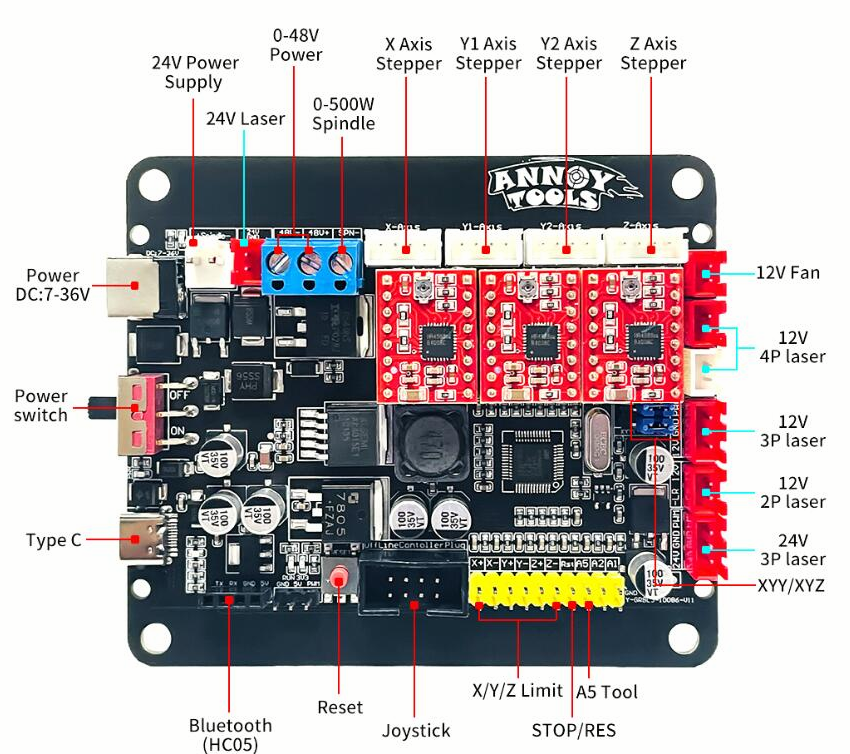
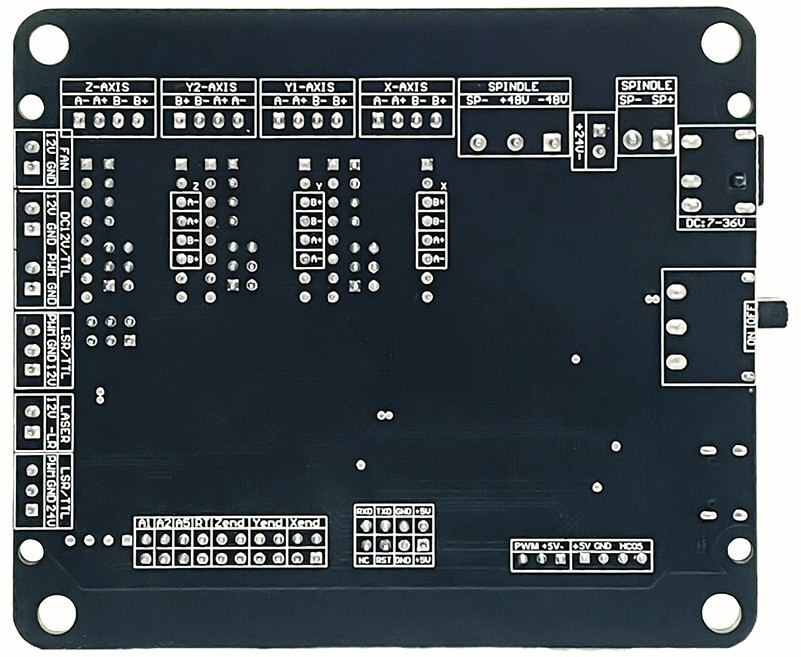 photos: ebay listing
USB configuration
Plugged into a USB-C port, it shows up as a USB device with descriptors:
  bDeviceClass            2 Communications
  bDeviceSubClass         0 [unknown]
  idVendor           0x0483 STMicroelectronics
  idProduct          0x5740 Virtual COM Port
  bcdDevice            2.00
  iManufacturer           1 tomeko net
  iProduct                2 LUNYEE_4axis_Control
… and supporting a
CDC data interface2.
In Linux it gets recognized as a serial adapter and appears as /dev/ttyACM0 (etc).
GRBL build
The $I command reveals it is running a custom build of GRBL 1.1f:
Monport
[VER:1.1f.20230316:������������������������]
[OPT:VMZHL,35,254]
some � omitted for clarity
CPU
This particular board uses a Gigadevice ARM Cortex CPU, probably a GD32F303VCT6 but I’m damned if I can read the inscription on this one even under a microscope.
I’m not at all clear on how I’d reflash this board if I wanted to change the firmware. I probably should have found an ESP32 based board if I’d wanted to do some software development, but this one was cheap and ticks all the boxes otherwise. If I get around to implementing polynominal trajectories I’ll probably make up my own board based on an Raspberry Pi Pico / RP2040 or similar.
Stepper Drivers
The board comes pre-populated with three A4988 drivers.
They have little heatsinks on top already and have
current limit trimpots which need to be set up
to suit your stepper motors, which means turning the trimpots
gently to achieve a V_REF which corresponds to a healthy maximum
current for your specific driver modules and stepper motors.
As shipped the board is set up to microstep where each microstep is 1/16th of a full step. Since my linear stages have 100 steps per mm this works out to:
| Microstepping | Microsteps per mm | μm per microstep |
|---|---|---|
| Full Step | 100 | 10 |
| 1/2 step | 200 | 5 |
| 1/4 step | 400 | 2.5 |
| 1/8 step | 800 | 1.25 |
| 1/16 step | 1600 | 0.625 |
Microstepping is not without its drawbacks, eg: reduced torque and repeatability, so we might end up going with 1/4 or 1/8 steps instead. This is controlled by the stepper driver jumpers hidden under the drivers themselves.
GRBL Settings
GRBL keeps a bunch of settings in NVRAM and these are the ones I changed:
| Setting | Purpose | Stock Value | New Value |
|---|---|---|---|
| $3 | Direction Invert (X,Y,Z) | 6 (invert Y and Z) | 3 (invert X and Y) |
| $20 | Soft Limit enable | 0 | 1 |
| $23 | Home dir invert | 7 | 7 (invert X, Y, Z) |
| $27 | Homing pull-off, mm | 2.000 | 2.500 |
| $100, $101, $102 | X,Y,Z steps per mm | 800, 800, 800 | 1600, 1600, 1600 |
| $110, $111, $112 | X,Y,Z max rate | 2000, 2000, 100 | 2400, 2400, 1200 |
| $120, $121, $122 | X,Y,Z max acceleration | 20, 20, 20 | 1000, 1000, 100 |
| $130, $131, $132 | X,Y,Z limit | 500, 500, 200 | 95, 95, 95 |
For some reason the Z axis is inverted in hardware.
I checked my stepper wiring many times and it just is.
So I invert X and Y ($3=3) to match, so that 0 is with the stage at the stepper end
and 100 is with the stage at the far end.
Homing direction is also inverted ($23=7), so the homing cycle travels to the
negative X, Y and Z direction which is where I’ve put the limit switches.
According to the Ebay ad the maximum speed is 120mm/s but the motors skip well below that
speed so I’ve set the maximum speed for all X and Y to 40mm/s ($110=2400, $111=2400)
and the Z axis which has to lift the camera I’ve set to 20mm/s ($112=1200).
Working out the maximum acceleration will take a bit of experimentation with the stages assembled into a machine. The Z axis is noticeably limited by the weight of the camera. Unfortunately, GRBL doesn’t allow you to set different limits in each direction.
Axis Connectors
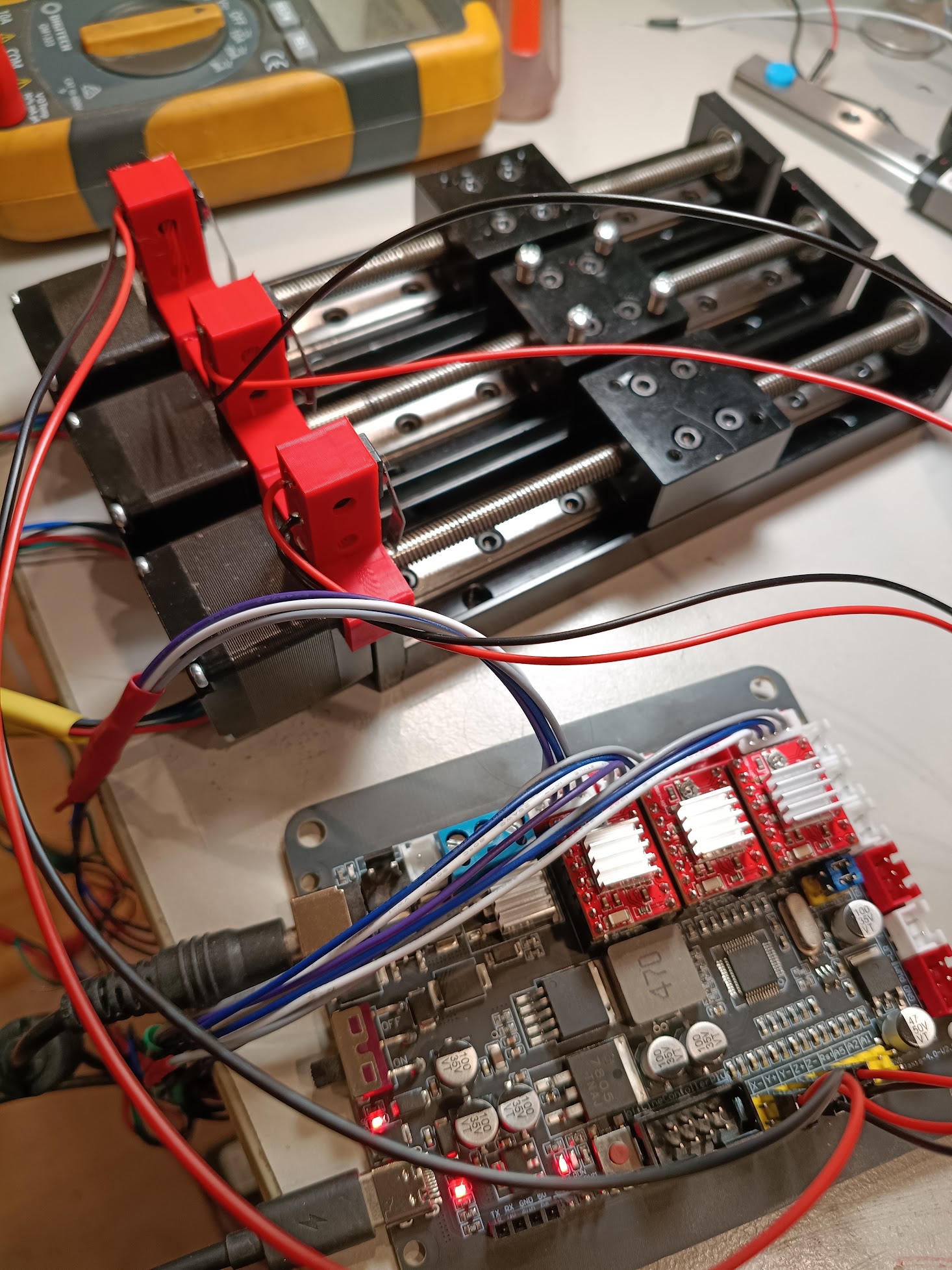
Each axis has it’s own JST XH2.5 with the following pinout. Except Y2 which is a reversed pinout of Y1. The steppers had bare wires and I had some spare pre-wired headers with Grey/Blue/Purple/White wires, so I just made up some frankencables.
| Pin | Phase | Header Wire Color | Stepper Wire Color |
|---|---|---|---|
| 1 | A- | Grey | Red |
| 2 | A+ | Blue | Blue |
| 3 | B- | Purple | Green |
| 4 | B+ | White | Black |
Using motors with pre-installed connectors would save a lot of messing about with solder and heatshrink.
Limit / Home switches
When the board first wakes up, it doesn’t know where the stepper stages have been left.
So it has to perform a homing cycle, and to do that it needs3 some switches to tell it when
each axis is ‘home’. Optionally you can also provide limit switches for the other
end of travel, but in this case I’m happy to trust the steppers to count correctly
and use soft limits ($20=1, $130=100, $131=100, $132=100).
The home and limit switches wire to two-pin “dupont” (aka “pin header”) connectors on the board. For now I’ve just used microswitches in a 3d printed plastic carrier which clips to the stepper, eventually the microswitches will get housed in a less ugly way.
Board Power
The stepper drivers are powered from the DC connector, which is
5.5mm OD / 2.5mm ID4
It is center positive and expects 7 - 36V.
I found a 19V 4A supply to suit.
Don’t forget to turn on the switch!
The CPU is, or at least can be, powered from the USB-C port while the motor power is off. There are a number of other power connectors on the board whose purpose is not entirely clear but are presumably for spindles, lasers, etc. I’m hoping to repurpose one of these for variable lighting power.
There are three red power LEDs on the board which might be helpful to know about:
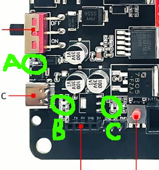
- A: Motor Power: labelled
PWR - B: USB-C Power: no label.
- C: Either Motor or USB-C Power: labelled
3V3
Does it work?
Yes! The three axis can be controlled independently or together using G-Code commands.
Note that GRBL starts a homing cycle with $H instead of the more common G28,
and depending on build options it might not let you do much until you run a homing cycle.
Next Steps
- printing a case for the board and some parts to hold the stages together and more elegant end stop switch holders.
- implementing smoother kinematics by sending way too much Gcode.
- work out how the 12V “laser pwm” port works.
Updated 2026-08-24
I’ve made a start on turning them into an XYZ setup …
… never mind the cable management! The base is just temporary too, just to hold everything aligned while I test out the kinematics.
I’m changing a few of the numbers in this article as I discover just how much of a limit this is!
Updated 2026-08-26
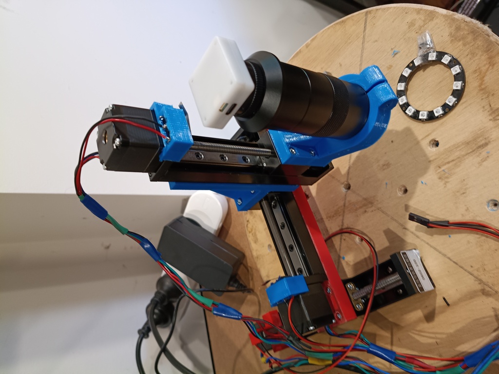
I’ve now got a microscope lens and USB-C camera attached and can move it around over a sample. Rather than using a focus servo I just set the focus by hand and then use the Z axis to move the whole lens and camera setup up and down to adjust the focal plane.
-
hurrah for standards! These are 1.1” (28mm) wide. The ones you see on most 3d printers are NEMA17, 1.7” (43mm) wide. ↩
-
Is there a proper standardized GCode device class? If there was, would anyone use it? We’re still haunted by the ghost of RS232. ↩
-
Unless you’re an Apple Disk II drive in which case you just smack into the end of travel 80 times and figure after that you must be home. ↩
-
Slightly chunkier than the typical 2.1mm ID which your junkbox is full of. Speaking of things which should have been better standardized … ↩